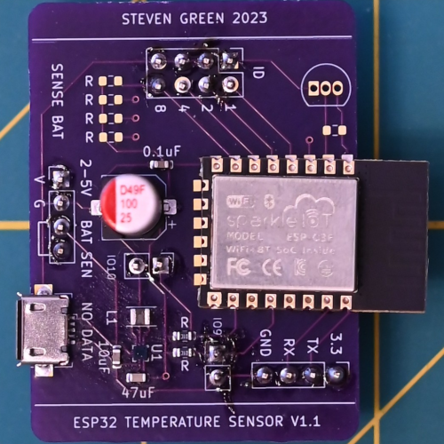
Temperature Sensor V1.1
I completed assembly of V1.1 of the sensor board. This version revised the power circuitry.
I applied techniques learned from the first version's assembly.
I placed the BGA power IC first. A thin layer of flux was applied to fix it to the board. Then the remaining SMT parts were placed. The board was baked hotter to ensure the paste flowed. The paste is getting old and may not be melting properly.
The ESP32 module did not align properly during the bake, but I don't expect it will cause an issue. The alignment may have resulted from the omission of paste on the southern pads; these pads float. Not soldering the pads was intentional to facilitate salvage of the ESP module in the event of another revision.
Also, the headers were moved to the underside of the board. This was done to make hand soldering easier. The large capacitor can is taller than the headers, and the board does not lay flat on the work-bench with the headers top-side, so the header's position was reversed.
As an added benefit, placing headers on the bottom allows attaching a 3.3v power module beneath the board. I purchased some 3.3v modules in the event assembly of the BGA parts failed.
The next steps are to program and test the board.
