Four point probe
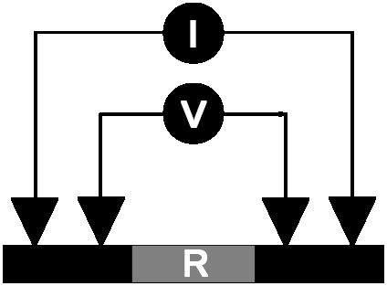
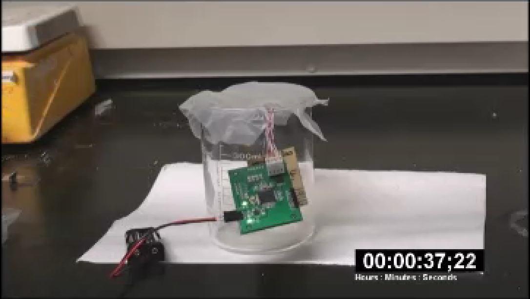
While researching resistive type Graphene sensors, I needed to demonstrate their portability. I implemented a battery powered 4-point measurement unit to interpret sensor readings.
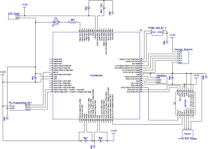
I created the measurement board leveraging an Analog Device AD7793 IC. This chip delivered most of the required functionality for a four point probe arrangement. When paired with a Microchip PIC32MX340 micro-controller using a serial peripheral interface (SPI), I was able to measure and interpret sensor data.
From the AD7793 data-sheet, I was able to write basic access routines in C to manage the IC from the micro-controller.
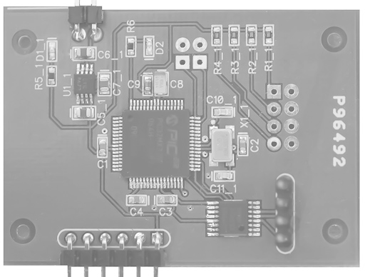
A showcase of the PCB, electrical schematic, and C firmware follows.


The circuit board was manufactured by Advanced Circuits, and hand assembled. SMT parts were re-flow soldered. Facilitating solder paste application, a stencil was obtained from Pololu Robotics & Electronics. After baking, solder bridges were removed using copper braid and a flat tipped soldering iron. Finally, through hole components were hand soldered.
Operation

C Firmware Source Files
/*******************************************************************************
 * File: main.c
 * Author: Steven Green
 *
 * Main routine for the AD7793 based demonstration board implementing a
 * four point probe.
 *
 * This code runs on a PIC32MX340
 ******************************************************************************/
#include "AD7793.h"

// configuration bit settings, Fcy=40MHz, Fpb=20MHz
#pragma config POSCMOD = XT, FSOSCEN = OFF, FNOSC = PRI, ICESEL = ICS_PGx1
#pragma config FPLLIDIV = DIV_2, FPLLMUL = MUL_20, FPLLODIV = DIV_4
#pragma config FPBDIV = DIV_1, FWDTEN = OFF, CP = OFF, BWP = OFF

// Let compile time pre-processor calculate the PR1 (period)
// the frequency of the PIC32 microcontroller
// lower frequencies keep the current requirements lower
// the power supply generates 50mA this should be safely
// within the limits
#define SYS_FREQ (8000000L) // an initial divisor
#define PB_DIV 1

// prescaler used for the timer generating timer interrupts
#define PRESCALE 256

// desired number of measurements per second
#define TOGGLES_PER_SEC 8

// the number of clock ticks required to generate the desired number
// of interrupts (measurements) per second
#define T1_TICK (SYS_FREQ / PB_DIV / PRESCALE / TOGGLES_PER_SEC)

// 1 second ticks
#define T2_TICK (SYS_FREQ / PB_DIV)

// I/O definitions
#define LED _RE4        // LED bit, 1=on 0=off
#define LEDTRIS _TRISE4 // LED in/out control bit

// according to AD7793 specs the ID returned by the chip will
// be 0xXB. X can change but the B is constant. The following two
// masks are used to determine that the ID is in fact 0xXB
#define ID_AD7793 0x0000000B
#define ID_ANDMASK 0x0000000F

// define the number of averages to take in order to base the
// change in resistance
#define AVERAGES 10

// the sensor will trigger when the resistance drops to
// this percentage of the starting average value
#define PERCENTAGE 0.99

// TEST_POT_SENSOR sets the code
//  ==1    expects the simulated sensor and blinks at a rate
//         proportional to the resistance in the range
//  ==0    expects an actual sensor and turns on an indicator
//         when the sensor resistance drops to a predefined value
#define TEST_POT_SENSOR 0

int data; // ADC Valueint average;
          // the average initial resistance measurementint trigger;
          // the value to trigger an positive indicationint OK;
          // flag to indicate the system is ready to collect data
void Delayms(unsigned t) {
  T2CON = 0x8000; // enable TMR2, Tpb, 1:1
  while (t--) {
    // t x 1ms loop
    TMR2 = 0;
    while (TMR2 < T2_TICK / 1000)
      ;

  } // Delayms
}

void Delaysec(unsigned t) {
  LED = 1;
  while (t--) {
    Delayms(1000);
  }
  LED = 0;
}

main() // MAIN LOOP
{
  OK = 0;    // make sure the interrupt does not read a value
             // until the AD7793 has not been configured
  data = -1; // initialize data to -1
             // the actual measurement will not be negative
  int i, t;
  int rData;            // used to clear the read buffer
  IEC0CLR = 0x03800000; // disable all interrupts
  SPI1CON = 0;          // stops and resets the SPI1.
  rData = SPI1BUF;      // clears the receive buffer
  initAD7793();

  // init the SPI for the AD7793
  // setup a timer interrupt to trigger on a tick
  // specified by T1_TICK this should correspond to
  // TOGGLES_PER_SEC measurements per seconds
  OpenTimer1(T1_ON | T1_SOURCE_INT | T1_PS_1_256, T1_TICK);
  ConfigIntTimer1(T1_INT_ON | T1_INT_PRIOR_2);
  INTEnableSystemMultiVectoredInt();

  // init LED
  LEDTRIS = 0; // LED pin output
  LED = 0;     // LED off
  delay();     // wait probably not required

  resetAD7793(); // send 32 high clocks to AD7793 to reset
                 // check the AD7793 ID
  // check that ID is correct for chip
  // bad SPI config will return wrong value
  int isValid = verifyAD7793();
  // main loop
  if (isValid) // AD7793 OK setup the chip
  {
    setConfig();                  // set AD7793 config register
    setIO();                      // set AD7793 IO register
    runMode();                    // put in run mode
    calibrateInternalZero();      // perform internal zero calibration
    calibrateInternalFullScale(); // perform internal high calibration
    runMode();          // put back in run mode (performing conversions)
    if (!errorStatus()) // check AD7793 error bit register
    {
      // wait 5 min before taking the average
      Delaysec(60 * 5);
      // set average and trigger values for the sensor
      // positive indication
      if (data == -1) {
        // get an average resistance at the start
        average = 0;
        for (i = 0; i < AVERAGES; i++) {
          average += readData();
        }
        average = average / AVERAGES;
        trigger = average * PERCENTAGE;
      }
      OK = 1; // allow the interrupt to update the ADC reading
              // main loop
      while (1) {
        if (TEST_POT_SENSOR == 1) {
          // blink the LED at a rate proportional to the resistance range
          LED = !LED;
          // equation to set the blink rate
          // specific to the test pot sensor
          t = (((data / 16777216.0 * 3.3) - 0.099) / 0.051) * 95000 + 5000;
          for (i = 0; i < t; i++)
            ;
          // variable delay
        } else {
          // turn on the LED if the value drops below
          // the lower resistance limit
          if (data < trigger) {
            LED = 1;
          } else {
            LED = 0;
          }
        }
      }
    } else {
      // turn on the LED to indicate an error
      LED = 1;
      delay();
      delay();
      delay();
      LED = 0;
    }
  } // main loop
  while (1)
    ; // loop do nothing
      // should not be here unless there is an error
} // MAIN LOOP

// timer interrupt
// read an ADC value periodically
void __ISR(_TIMER_1_VECTOR, ipl2) _TimerHandler() {
  int i;
  if (OK == 1) // the chip is configured properly
               // if not OK do not read a value from the AD7793
  {
    data = readData(); // read an AD7793 value
  }
  mT1ClearIntFlag(); // clear the interrupt flag
}
/*****************************************************************************
* File: AD7793.c
* Author: Steven Green
*
* Description: Source file for basic functionality provided for the AD7793
* chip.
*
* AD7793 Access Library
*****************************************************************************/
#define CS _RF5 // select line for Serial AD7793
#define TC _TRISF5 // tris control for AD7793
// peripheral configurations
#define SPI_CONF 0x8060 // SPI on, 8-bit master,CKE=0,CKP=1,SMP=1
#define SPI_BAUD 24 // clock divider Fpb/(2 * (SPI_BAUD+1))
// send one byte of data and receive one back at the same time
int writeSPI1(unsigned int i) {
while (!(SPI1STAT & 8))
;
SPI1BUF = i; // write to buffer for TX
while (!(SPI1STAT & 1))
;
return SPI1BUF; // read the received value
}
int readSPI1() { return SPI1BUF; }
void initAD7793(void) {
CS = 1; // de-select the Serial AD7793
TC = 0; // make CS pin output
SPI1BRG = SPI_BAUD; // use FPB/4 clock frequency
SPI1STATCLR = 0x40; // clear the Overflow
SPI1CON = SPI_CONF;
// SPI ON, 8 bits transfer, SMP=1, Master mode
// init the SPI1 peripheral
}
// initAD7793
// define CMD_READ_ID_REGISTER 0x60
#define ID_AD7793 0x0000000B
#define ID_ANDMASK 0x0000000F
void delay() {
int i;
for (i = 0; i < 100000; i++) {
} // delay
}
// reset the AD7793 to its default settings
// this is recommended for startup
int resetAD7793() {
// write 32 high bits to the AD7793
CS = 0; // select the AD9973
writeSPI1(0xFF);
writeSPI1(0xFF);
writeSPI1(0xFF);
writeSPI1(0xFF);
CS = 1; // unselect the AD9973
}
int verifyAD7793() {
int i;
CS = 0; // select the AD9973
i = writeSPI1(0x60); // next op read from the ID register
i = writeSPI1(0xFF); // read the 8bit register
CS = 1; // unselect the AD9973
return ((0x0F & i) == 0x0B);
}
// read the status register
int getStatus() {
int i;
CS = 0; // select the AD9973
i = writeSPI1(0x40); // next op read from the status register
i = writeSPI1(0xFF); // read 8bit status register
CS = 1; // unselect the AD9973
return (i & 0xFF);
}
// check if the error bit in the status register is set
int errorStatus() { return ((getStatus() & 0x40) != 0); }
// returns bits indicating the ADC channels being read
// there are three different registers
int getChannels() { return (getStatus() & 0x07); }
int setConfig() {
int i;
CS = 0; // select the AD9973
i = writeSPI1(0x10); // next op write to config register
i = writeSPI1(0x10); // write high 8 bits
i = writeSPI1(0x00); // write low 8 bits
CS = 1; // unselect the AD9973
return (i & 0xFF);
}
int runMode() {
int i;
CS = 0; // select the AD9973
i = writeSPI1(0x08);
i = writeSPI1(0x00);
i = writeSPI1(0x01);
CS = 1; // unselect the AD9973
return (i & 0xFF);
}
int setIO() {
int i;
CS = 0; // select the AD9973
i = writeSPI1(0x28);
i = writeSPI1(0x01); // both current sources pin 1, 10uA
CS = 1; // unselect the AD9973
return (i & 0xFF);
}
int readData() {
int i;
CS = 0; // select the AD9973
writeSPI1(0x58);
while (_RF2 != 1)
;
i = (writeSPI1(0xFF) << 16); // H
i |= (writeSPI1(0xFF) << 8); // M
i |= (writeSPI1(0xFF) << 0); // L
CS = 1; // unselect the AD9973
return i;
}
int calibrateInternalZero() {
int i;
CS = 0; // select the AD9973
writeSPI1(0x08);
while (_RF2 != 0)
;
writeSPI1(0x80); // H
writeSPI1(0x01); // L
CS = 1; // unselect the AD9973
return i;
}
int calibrateInternalFullScale() {
int i;
CS = 0; // select the AD9973
writeSPI1(0x08);
while (_RF2 != 0)
;
writeSPI1(0xA0); // H
writeSPI1(0x01); // L
CS = 1; // unselect the AD9973
return i;
}