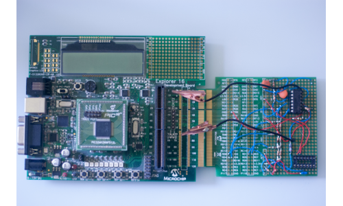
Locked-in amplifier 1.0
Derived from Microchip’s AN1115 application note, this experiment implemented a locked-in amplifier circuit and C firmware running on a microcontroller to measure a resistance.
Initially implemented by Microchip using a dsPIC, I ported the logic to a PIC32 running on an Explorer 16 Development board. A resistor ladder circuit was implemented on a daughter board and excited using DIOs from the microcontroller. It generated a 25kHz sinusoidal signal that was passed through a resistance.
As opposed to a simple multimeter, a locked-in amplifier measures sinusoidal excitation rather than direct current. By tracking a single frequency, where noise is distributed over many frequencies, a more accurate measurement can be made of changes in resistance than that from a DC voltage. If the changes in resistance are small they could be obscured by noise.
My experiment differed slightly from the application note. I did not use a Wheatstone bridge and measured an individual resistor. A Wheatstone bridge could have been used to increase the magnitude of a change in measurement, however lacking resistive sensors I simplified the experiment and just measured passive resistors.
Using a 25kHz excitation the in-phase and quadrature components of the signal were determined programmatically and yielded amplitude and phase values for the resistors.
The measurement unit was calibrated against a desktop multimeter and accurately measured resistances up to \(1M\Omega\).
In retrospect I should have tested the measurement of resistance of the locked in amplifier in comparison to the digital multimeter in the presence of noise.
I am in the process of repeating the experiment with a new daughter board that also adds noise to the measurement for a more complete picture.
