Locked-in amplifier 2.0 plan
Inspired by the short-comings of my first locked-in amplifier experiment, this is my plan to revisit the subject.
My main oversight in the first experiment was not quantifying the difference between measurements, both with and without noise, and to what degree the noise would have influenced outcomes.
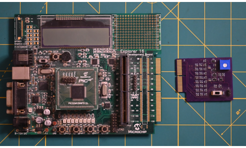
I am writing this plan, having already taken an initial pass at a new circuit. In that I had implemented a simple daughter board that I had expected would generate noise and a sine wave, via a ladder circuit, then mix the two. Unfortunately, I took a shortcut and parts that had worked in version 1.0, did not function well. Further, I should have run some tests of the noise generation circuit prior to incorporating it into the design. On the new circuit I tried to include too much at once.
Going forward, I will design three separate parts to be wired together: a sine signal generator, noise generator, and a signal mixer.
- The locked-in amplifier needs to generate a sine wave synchronised with the measurement logic; the frequency is chosen to be 25kHz, the same frequency used in the application note. This ladder circuit needs to use fewer bits of resolution (4 instead of 8) to allow an 80Mhz processor enough time to toggle digital outputs on the microcontroller. The resulting wave can be smoothed using a low-pass filter. Further, ladder output needs to be buffered to prevent adverse effects to other parts of the circuit. This part should provide test points for measuring signals and provide access to ADCs, not necessarily limited to those on the microcontroller to enable the device to operate as a DAQ for noise measurement. Due to the ADC requirement this board should follow development of the noise generation component.
- The noise generation circuit needs tested in isolation to ensure it will be able to generate varying levels of white noise. A simple Zenner diode based noise generation circuit is desired. Different voltages need tested to determine possible noise magnitude and quality. Doing the noise circuit first will enable me to determine the oscilloscope's effectiveness. If the scope is ineffective, ADCs in the microcontroller or added could serve as a simple data acquisition device.
- The third and final part is a simple mixing circuit to merge the noise and signal. It may be convenient to plug the mixer into the ladder board as a sub-board. Having the mixer separate will make it possible to use different mixing circuits if needed.
