Senior Capstone 2010
Senior Capstone 2010
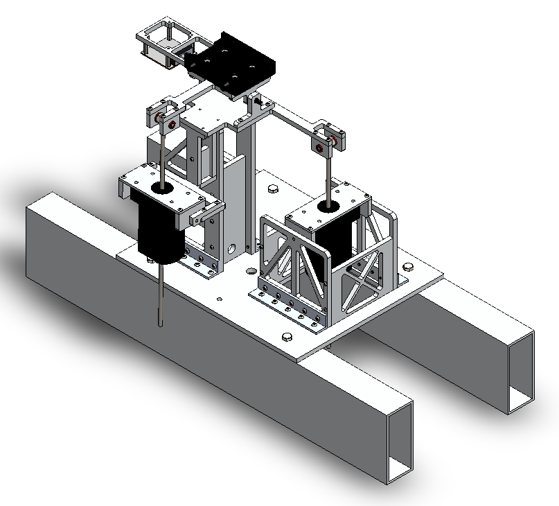
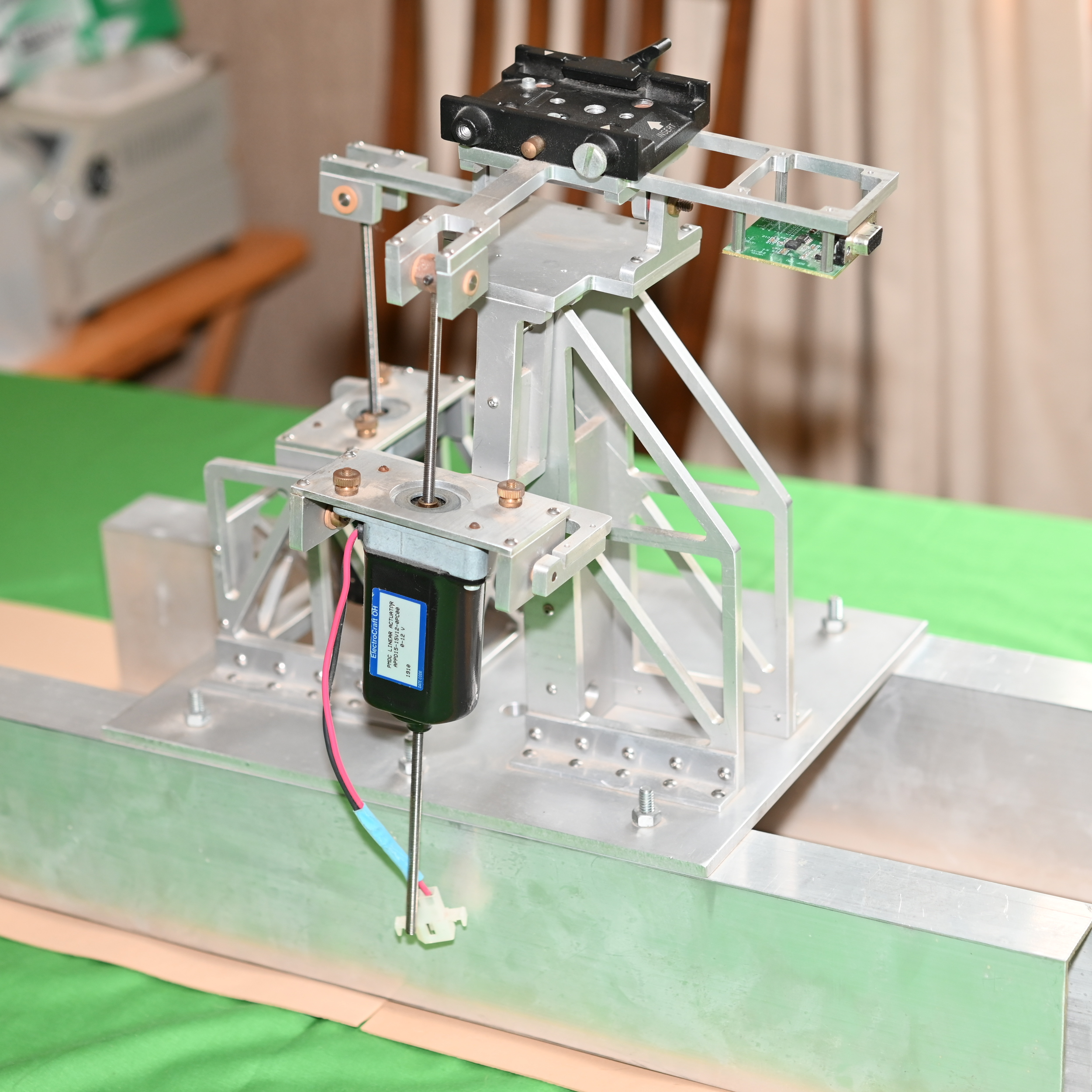
I designed a electro-mechanical platform to keep a camera level when mounted on a vehicle for my senior capstone project at UMass Lowell in 2010. The self-leveling platform was designed to level a camera, for the purpose of taking still images, from a moving vehicle. The intent was that the platform would be mounted to a roof rack.
Inspiration was drawn from a personal desire to take high quality pictures while driving on roads where setting up a camera would be impractical.

In chronological order the project went through the following steps:
- The project was chosen as the most reasonable and desirable idea for a senior capstone. Other candidates included a variety of robotics, however these required more hardware and would cost more to prototype as well as more complicated software.
- Drive mechanisms were explored including BLDC motors, steppers and linear actuators. My personal desire to direct drive the axis of the platform using BLDC motors or steppers gave way to linear actuators, which simplified the design and reduced the costs of the platform. While not perfect the linear actuators solved a number of issues, most importantly the platform would stay where it was left in case of power loss.
- Determination of the physical dimensions and the physical limits of the product required real measurements. The platform used levers to adjust pitch and roll and the lengths of the levers and angular range of the platforms were computed from measurements made in a moving vehicle. A control board was designed that employed a PIC32 micro-controller that read voltages from accelerometers and gyroscopes, and recorded the data to a flash drive. This was implemented using a MicroSD card slot via the SPI bus, and a simple 16 bit FAT file system.
- The sensor board is mounted to the platform in the final product. Not knowing true accelerations and angular rates a car would undergo as it moved up and down hills, the assumption was made that the rates would be on the lower end of the available chips when under expected conditions cars rides smoothly.
- Once the control board and sensor board were designed, fabricated, and assembled motion tests were performed. Powered off the car's electrical system, the electronics were used to measure a particularly hilly area of Hopkinton State Park in MA. Outputs were recorded and later processed on a computer using Excel and MATLAB to determine the extrema of angles and rates as the car traversed the terrain. These initial measurements led to the physical design of the device. The mechanical design encompassed creation of a platform capable of moving to the measured limits with a reasonable margin of safety.
- Linear actuators were selected based upon three primary characteristics: the rates at which the motors could drive the platform, the range of motion, and how were the actuators controlled. Motors were chosen where rate of motion was proportional to voltage. Voltage control enabled the PID algorithm to output a single value to the motor drivers.
- The mechanism itself was designed to be cut from a single piece of aluminum plate stock 1/4 inch thick on a CNC Mill. The 1/4 inch plate was thick enough to enable screws to traverse the edges.
- Several holes were made through the platform to enable mounting to a vehicle with safety lines.
- Once assembled the device was built and programmed. A PID loop was implemented, tuned and tested, and was effective where extra accelerations were limited. It was hoped that a Kalman filter could correct acceleration effects on the accelerometers by joining the accelerometer and gyroscope measurements. The Kalman filter was not completed and required further research.
- At the end, the platform, electronics and firmware had been tested successfully. The platform moved appropriately in tilt tests.
This project was presented in fulfillment of my senior capstone requirement in front of the mechanical engineering class in 2010. Final assembly was completed soon after as the motors and other parts arrived later than hoped.
