Sensor Board
Sensor Board
I designed a electro-mechanical platform to keep a camera level when mounted on a vehicle for my senior capstone project at UMass Lowell in 2010. The project required a sensor to be mounted with the camera to determine its orientation.The specifications for the sensor were:
- 3 axis accelerometer IC and 2 axis gyro IC
- Provide analog outputs for communication with ADCs
- Be securely mountable to the platform
- Use a D-Sub connector for wiring to the control board
The combination of the accelerometers and gyros in a single package is called an inertial measurement unit (IMU). IMUs are available in hobby versions and those meant for rugged use. The boards meant for hobby use were within the budget. The hobby board provided 9 in-line through holes for wiring and two mounting holes on the edge. To facilitate the connection of the board, pin connections were created to allow quick connection of cables. The purchased board functioned, however it became apparent the unit would be difficult to mount securely from one edge. While testing the board the connector, which was symmetric, was reversed and it short circuited resulting in damage to the board.
At the time this occurred the board was temporarily unavailable. Desiring a more complete and error resistant solution, allowing for selection of filter values, better connectivity and better mounting options, focus shifted to a custom solution.A custom solution offered a learning experience in product development. Custom building the sensor board allowed for the selection of components with sensitivities specific to the needs of the project and output filter cutoff frequencies were customizable. Also, the board could be designed to mount at four corners rather than two points on one edge. D-Sub connectors could be used to ensure ensure it would be properly connected.
This approach took more time however.
The board required design, layout, manufacture, assembly and testing, but considering potential learning, it was pursued.
The sensors were defined first. Initial estimates of acceleration and angular velocity were made from observations made during a typical journey in a scenic area. These were rough estimates intuition deemed close enough for a prototype.
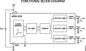
The sensors needed to measure the acceleration due to gravity to determine the downward vector. An accelerometer was chosen that measured accelerations along the X, Y and Z axis, an Analog Devices “ADXL335”. This accelerometer had \(\pm3g\) sensitivity, and could survive \(10000g\) shocks, deemed sufficient for mounting on a moving vehicle.
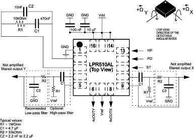
Since the measurements would be altered by acceleration and braking, an attempt was planned to correct the error. A two axis gyro was intended to combine with software filtering to compensate for the error. A STMicroelectronics LPR510AL dual axis gyro was used. It had a sensitivity of \(\pm 100^\circ/sec\).
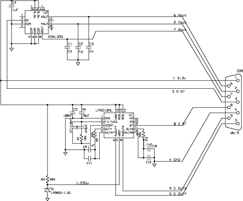
The accelerometer and gyro were powered of a common 3.3V DC source. The supporting circuitry was taken from the IC datasheets. Figures 1 and 2 show the recommended circuits from the manufacturer's datasheets.
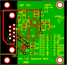
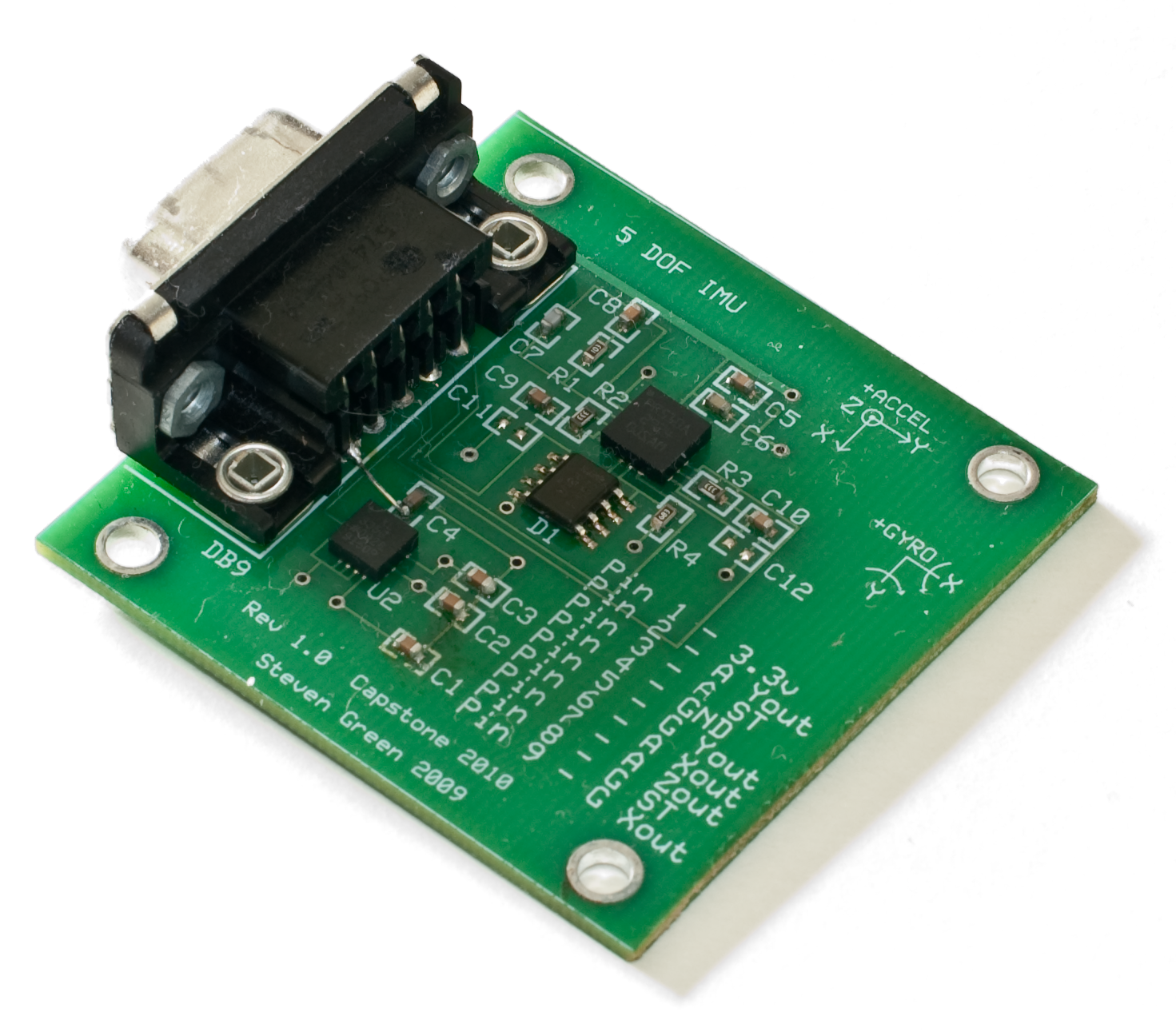
Assembly was performed by hand. Using a stencil solder paste was applied to the pads and the components were placed using tweezers. A small IR oven (T-962) was used to melt the solder. The final assembled sensor board is shown in Figure 5.
